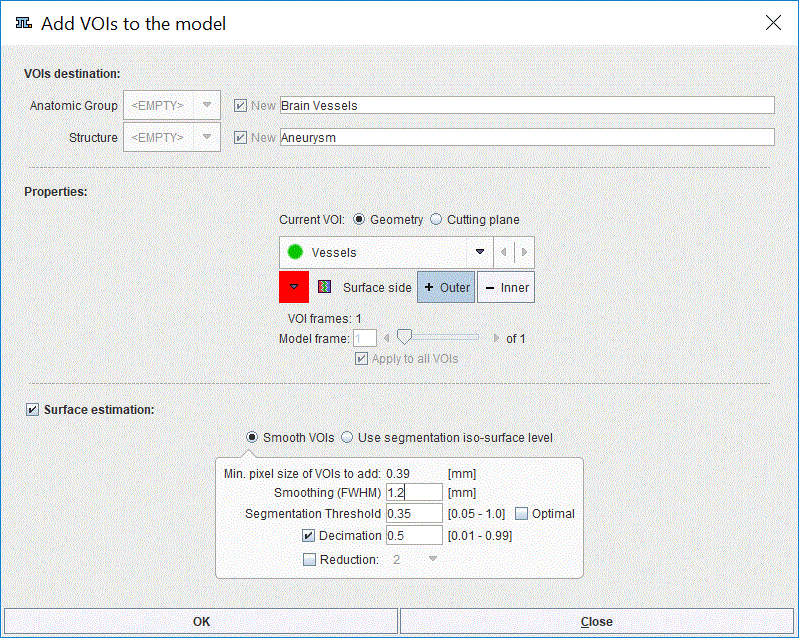
In the Properties section of the model builder interface, select the Geometry radio button for the Current VOI .

The appearance of the model builder interface is adjusted according to the Current VOI setting. The window is organized in three main sections:
1.VOIs destination: allows defining the Anatomic Group and the Structure.
2.Properties: allows defining the VOIs properties for the model.
3.Surface estimation: allows defining settings to build the STL structure of the model.
VOIs Destination
The VOIs destination section requires definitions for the Anatomic Group and Structure. When VOIs are added to the model for the first time, these settings are <Empty> and New names need to be provided in the dedicated field. To this end, the Brain Vessels and the Aneurysm were set as Anatomic Group and Structure respectively.
The settings available in this section are summarized in the table below:
Anatomic Group |
Corresponds to the highest hierarchy level in the model tree structure: the Group Allows defining the model Anatomic Group to which the VOIs will belong. To define a new Anatomic group the New checkbox has to be enabled and the name specified in the dedicated text field. Confirm and add the entry to the list with the Enter button on the keyboard. The drop down arrow becomes active when more than one anatomic structure was defined. It allows selecting among the currently available Anatomic Group. |
Structure |
Corresponds to the second hierarchy level entry in the model tree: the Structure. Allows defining the model Structure to which the VOI will belong. To define a new Structure the New checkbox has to be enabled and the name specified in the dedicated text field. Confirm and add the entry to the list with the Enter button on the keyboard. The drop down arrow becomes active when more than one structure was defined. It allows selecting among the currently available Structure. Note: Multiple Structures can belong to the same Anatomic Group. To this end turn off the New checkbox for the Anatomic group, select one of the Anatomic Group available on the list and proceed with the definition of a new Structure as described above. |
Properties
While adding VOIs to the model as Geometry, the various Properties are defined in the dedicated section. In the example above the VOI color is set to red while the rest of the properties are the default ones.
The properties settings are summarized below:
|
Allows changing or editing the color of the VOI(s) to be added to the model structure. |
|
Allows setting the VOI(s) as an Outer or Inner surface. For example the epicardium and endocardium in the heart muscle. |
|
When enabled applies the same properties to all the VOIs available on the Current VOI selection list. Please note that more than one VOI at the time can be added to the model. |
VOI frames |
Provides information related with the VOI type: •a value of 1 indicates the user is adding static VOIs to the model. •a value >1 indicates the user is adding a dynamic VOI to the model |
Model frame |
Allows setting the model frame where the VOIs will be added. In case of dynamic VOIs the number indicates the starting frame of appearance in the model. Please note that the frame number for the model has to be defined previously. |
Surface Estimation
The Surface estimation section allows defining characteristics for the STL model structures. While adding VOIs to the model surfaces (STL files) are generated automatically with the Surface estimation box enabled. These STL files will be stored in the model folder and will be used for 3D model presentation. Generating them will allow rendering faster the whole model in 3D.
Note:
Please note that these STL files are not the STL files used as surface meshes while creating CFD case process.
With Smooth VOIs radio button active the settings are as follows:
Min pixel size of VOI to add |
Displays the pixel size [mm] in the data |
Smoothing (FWHM) |
It is a Gaussian filter and allows smoothing the data before creating the STL structure. The default value corresponds to the pixel size in the data. It is recommended to use a smoothing value 3 times the minimum pixel size. Note: Please note that for complex VOI shape less smoothing should be applied |
Segmentation Threshold |
All pixels with the value above the threshold are included in the segment. The default value is 0.35. When the Optimal checkbox is enabled the threshold will be calculated automatically such that the volume of selected VOIs is preserved. |
Reduction |
If enabled, allows creating simplified mesh based on data simplification. The defaults value is 2 and is representing the smallest value to be defined. Initially, the program will use this number and multiply the pixel size of the data with this value. Finally, the mesh will be generated on the new data. It is a faster procedure and the results will consist in mesh being less precise. Please note that if only this checkbox is enabled the generated files will be bigger and change in topography of the mesh will occur. |
Decimation |
Allows simplifying the mesh by removing triangles from the surface mesh without changing the mesh. Please note that in such case the simplification procedure is done after the mesh is created. The defined value should be between 0 and 1. The number represents percentage of the triangles to be thrown out. Usually „0.5” is a good compromise. The smaller the number of triangles, the faster is the 3D visualization. It is a slow procedure which generates smaller files. Decimation only changes the number of STL nodes, particularly the vertices of the surface mesh. However, no change in the mesh geometry occurs, preserving thus the mesh topology. |
In alternative, the Use segmentation iso-surface level radio button can be used. It is recommended to use this option when the VOI was outlined using the isocontouring VOI tool and the image data loaded is the image data on which the VOI was created. With these two conditions fulfilled, the threshold value used for VOI isocontouring has to be set as Original Segmentation Threshold.
Note:
The iso-surface is recommended to be used for big geometries like skull.
In the current example the Smooth VOIs radio button is enabled. The Smoothing (FWHM) parameter is set to 3 times the pixel size (1.2 mm), Decimation is set to 0.5 while reduction is avoid.
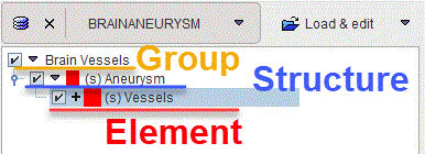
Activate the OK button to start adding the VOI available in the Current VOI list to the model. The VOI will correspond to the lowest hierarchy level in the model tree structure: the Element. STL structures are auto-generated and saved for each VOI added to the model. This is encoded in the model tree by the letter s between round brackets which precede the Element and the Structure name. The result of the above processing is illustrated below:
