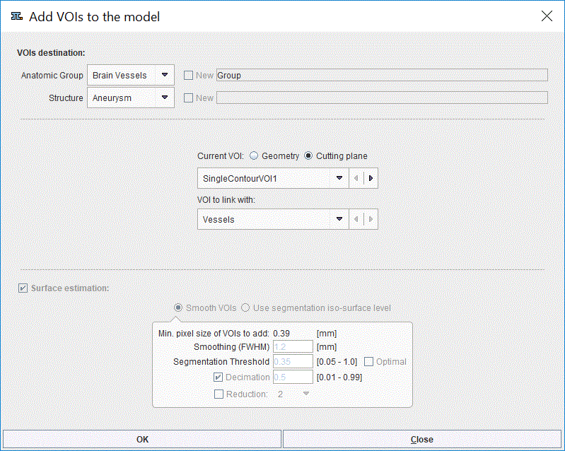
In the Properties section select the Cutting plane radio button for the Current VOI.

This setting can be used for single contour based VOIs. Particularly, only single contour VOIs outlined in the VOI definition step can be added to the model as predefined cutting planes. These will be used in the creation of the CFD case. Cutting plane VOIs can only exist when linked with existing structure. Therefore it is recommended to create single contour VOI based on an existing multicontour VOI available on the VOI list. This can be easily achieved creating an empty VOI in the list and pasting a single contour from the VOI of interest. Please note that location of the predefined cutting planes cannot be modified in the creation of the CFD case.
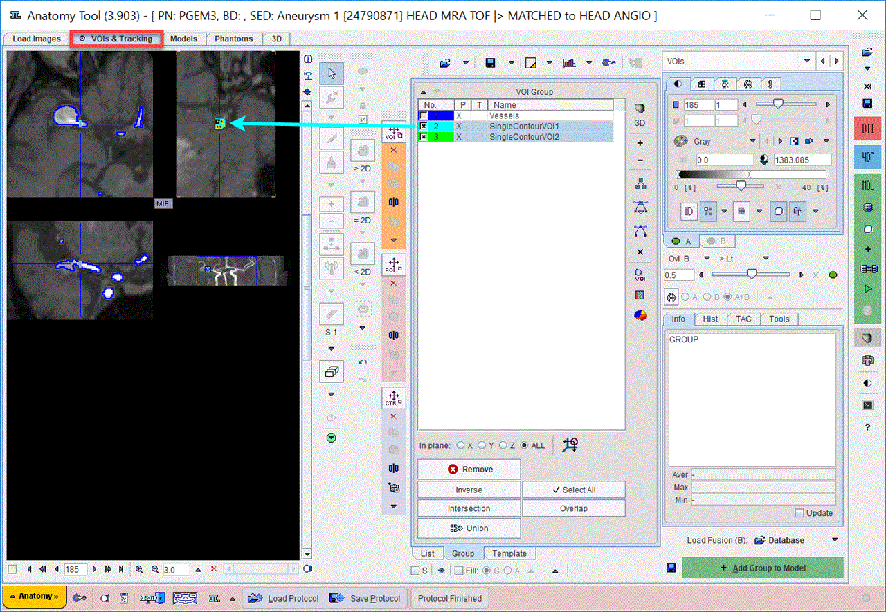
In the example below, two single contour VOIs, SingleContourVOI1 and SingleContourVOI2 were created based on two contours belonging to the Vessels VOI:

It is mandatory to add the linking VOI to the model as Geometry beforehand. Please note that in the example above all VOIs are outlined in the same direction: X.
Note: The direction of the VOI to be added as a cutting plane is required be the same as the VOI to be linked with.
In the model builder interface only the two upper most sections are active:
1.VOIs destination: allows setting to which Structure in the selected Anatomic Group the VOI will be linked to as a cutting plane.
2.Properties: allows selecting the VOI to link with the selected cutting plane.
The OK button is activated to start adding the cutting plane to the model. The cutting plane will be linked to the selected Element in the model tree structure.
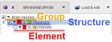
The result of adding a VOI as a cutting plane is illustrated below:

The VOI added as a cutting plane does not appear as an additional Element in the model tree. It is linked with the specified Element and encoded in the naming procedure by the cp entry. The plane will be available in the workflow of the CFD creation.