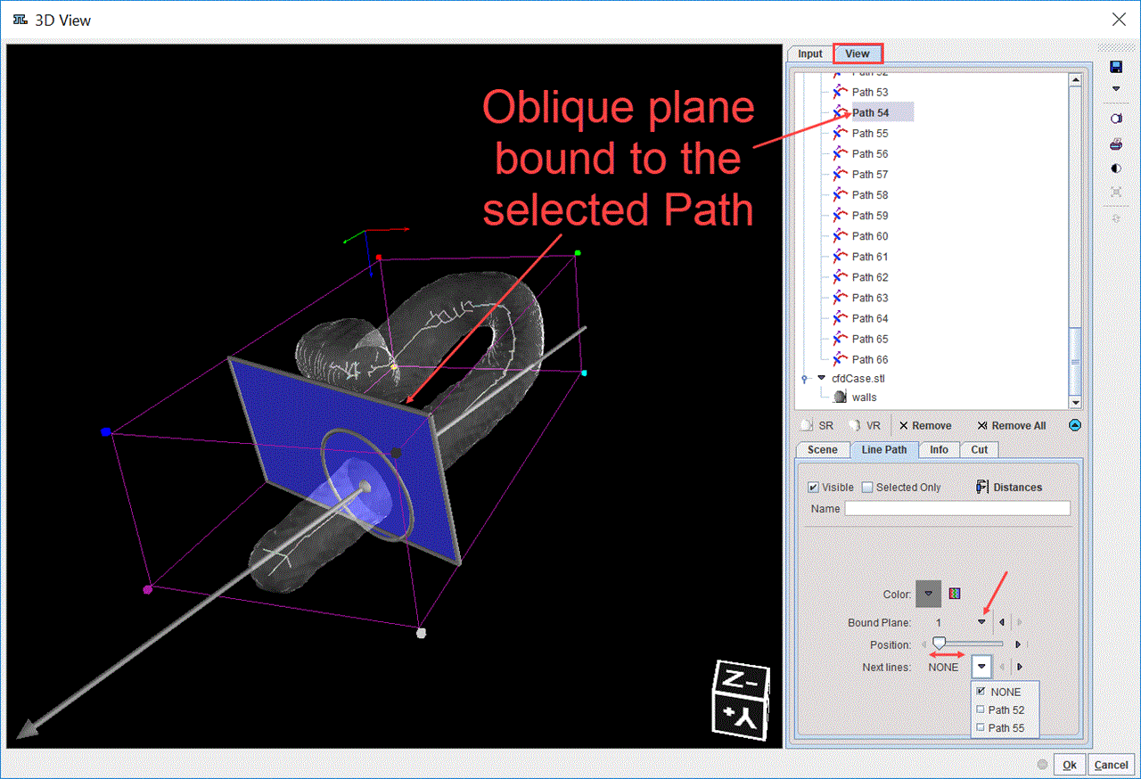
The 3D interface for the definition of the cutting planes using generated paths is illustrated below:

The paths are representing the skeletons components and are immediately available in the View tree when the 3D interface appears.
In the example above one oblique plane 1, was used to create the cutting planes on the selected surface render object: the walls. The blended transparency was enabled for the walls in order to allow the visibility of the skeleton paths. The Path 54 is selected in the View tree and the Bound Plane selection is set to the oblique plane 1. The oblique plane is placed orthogonally to the vessel skeleton as soon as it is bound to a selected path. The Position slider allows moving the plane along the active path while preserving the orthogonality.
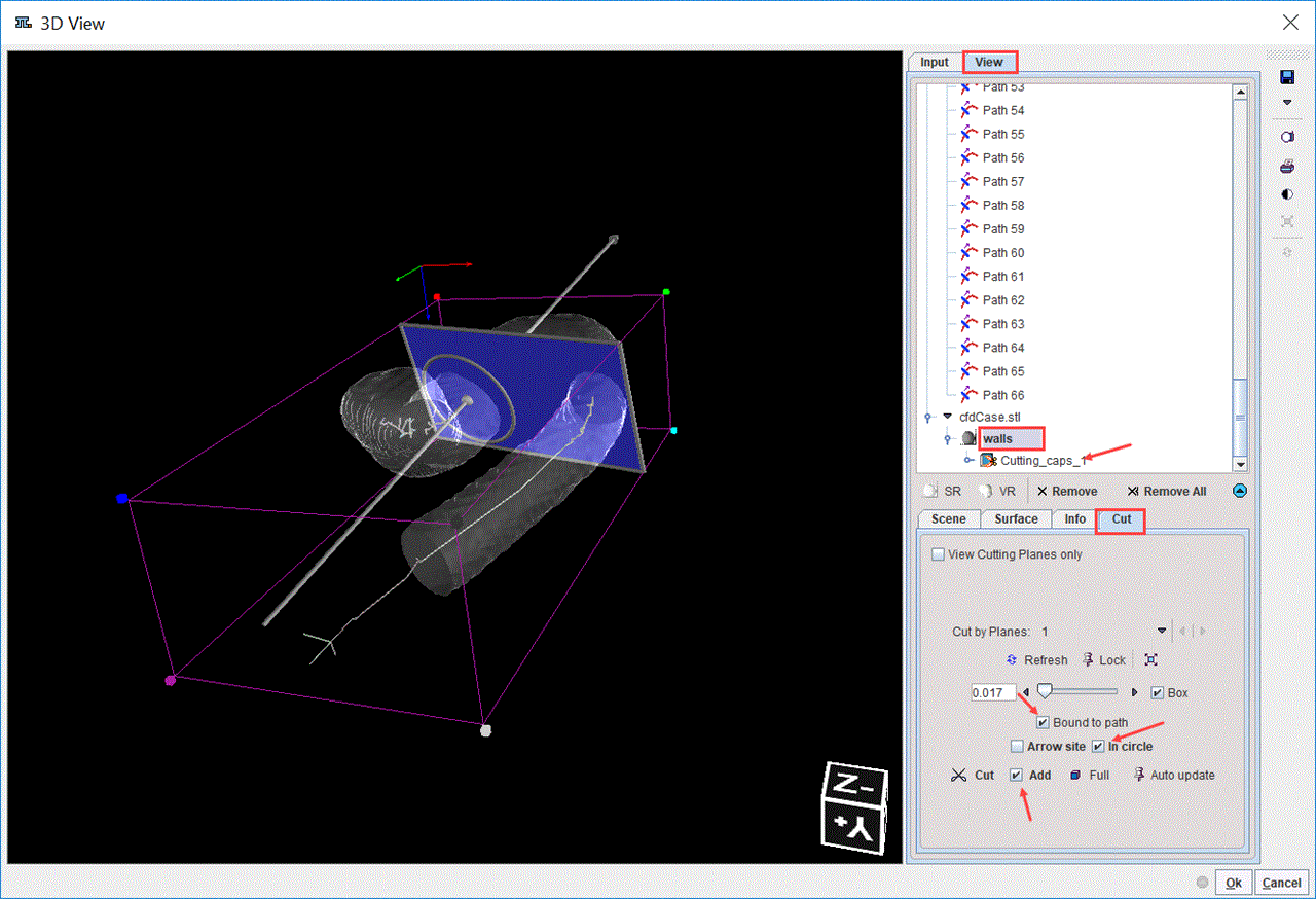
To cut a part from the SR object used for the skeletonization select the SR object (walls) in the View tree and subsequently the Cut tab belonging to this object (NOT the Cut tab of the Planes object). With the Bound to path, Arrow site and In circle boxes enabled the Cut button is activated. The Cut button starts a process which clears all information of the selected object on the defined side and area and refreshes the rendering scene. The part of the SR object on the same side as the arrow head is cut from the scene. There is now an indication in the object tree which objects have been cut:

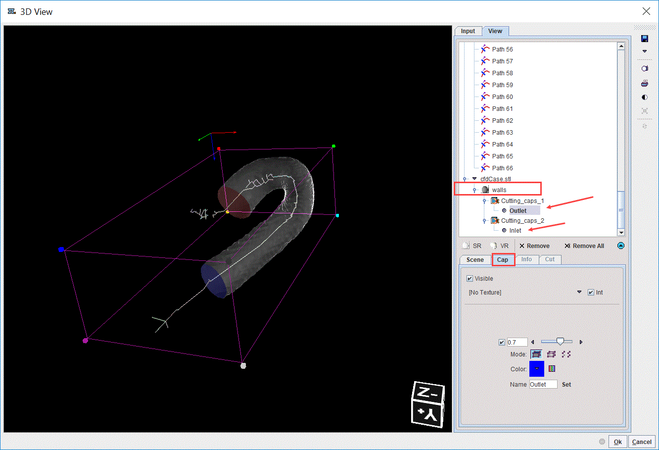
The same oblique plane is used to define another cutting plane for the walls. The plane is bound to the Path 33. With the Bound to path, In circle and Add boxes enabled the Cut button is activated. With the Arrow site box disabled the part of the object on the opposite side of the arrow head will be cut. The final scene is illustrated below:

The resulting cutting planes are renamed to Outlet and Inlet editing the Name field followed by the activation of the Set button.
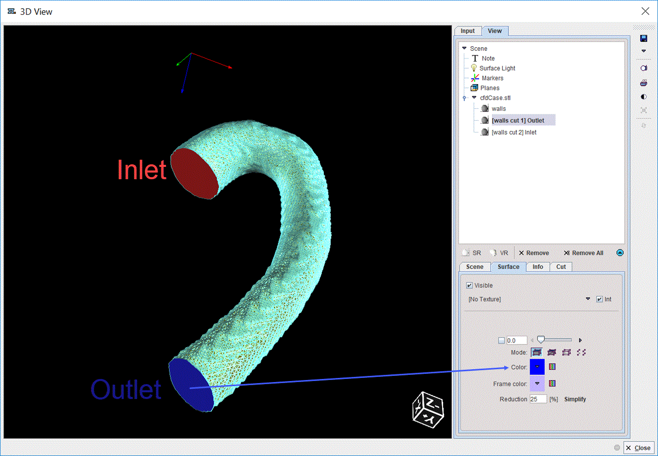
Close the 3D interface with the OK button to generate the surface mesh. The results are shown in a 3D window. It allows exploring interactively the generated surface mesh as illustrated below:

Close the window and continue with the VM creation. The cutting planes will be used to define the boundary conditions for the CFD simulation.