The following steps are described using the Aneurysm 1 series of the PGEM3 subject available in the Pmod database.
Image Definition in Model Settings Window
When closing the CREATE Model window with Ok, another window appears, requesting image(s) definition:

The Edit mode tab allows defining two images: image A and image B.
Image A is the image that will be loaded when the Load & edit button is activated. It will be considered the basic image for editing VOIs. Image B, if defined, has to be matched to the image A beforehand, as the two will be shown using the fusion mode on the Images page.
With the Reorient to Anatomical Position box enabled, the images are brought into the radiological HFS orientation after loading.
Use the ![]() button to add a VOI file to the model at this stage. Please note that the VOIs have to be previously outline and saved as .voi file on image A or B.
button to add a VOI file to the model at this stage. Please note that the VOIs have to be previously outline and saved as .voi file on image A or B.
The Reference Image tab provides additional settings:

It allows defining a reference image which can be A or B or any other image in the same space. The Image file name field allows assigning a name to the image. The default name is assigned based on the model name followed by the suffix _image_1 as shown in the example above. The preview button ![]() allows visualizing the images set for the model. Enable the Reorient to Anatomical Position box to bring the image into the radiological HFS orientation. Activate the Copy to model as Reference Image (Nifti) green button to copy the image in the model folder as a Niftii image. A confirmation dialog will appear asking the confirmation of the saving procedure. Close the dialog with YES to save the reference image in the model folder.
allows visualizing the images set for the model. Enable the Reorient to Anatomical Position box to bring the image into the radiological HFS orientation. Activate the Copy to model as Reference Image (Nifti) green button to copy the image in the model folder as a Niftii image. A confirmation dialog will appear asking the confirmation of the saving procedure. Close the dialog with YES to save the reference image in the model folder.
In the example above the same image was defined as image A and as Reference Image.
Activate the Load & edit button to proceed to the VOI definition step:

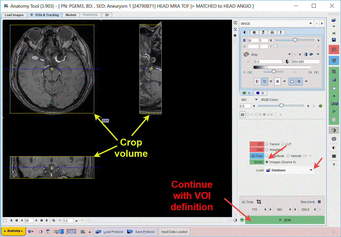
The program switches to the VOIs & Tracking page, Image sub-page while loading and displaying the image defined as A:

The images data with large field-of-view can be reduced in order to save RAM and optimize processing. This can be achieved enabling the Crop box. A yellow crop volume appears on the image. Place the yellow crop volume by clicking in the center of the area of interest such that is fully enclosed. The edge Size in [mm] can be adjusted for each direction by selecting the size in the corresponding list. The Crop![]() button initiates cropping, whereby the original data are replaced. If cropping is not initiated manually, a request will be shown when proceeding to the VOIs step.
button initiates cropping, whereby the original data are replaced. If cropping is not initiated manually, a request will be shown when proceeding to the VOIs step.
Note:
To use the Reference image for the VOIs definition select the corresponding entry under the Load & edit selection list, as illustrated below:

Image Definition by Model Image Loader
When no image is defined in the Model Settings interface, after pressing Load & edit button, the user will be asked to provide such configuration. In case there is no intention to provide such configuration, the user has to manually select the VOIs & Tracking page Image sub-page, enable the Model radio button and load an image configuring the available Load button. This image will be used for the VOIs definition in the next step.
Continue the VOI definition activating the VOIs action button.