The Preview interface for the definition of the cutting planes is illustrated below:
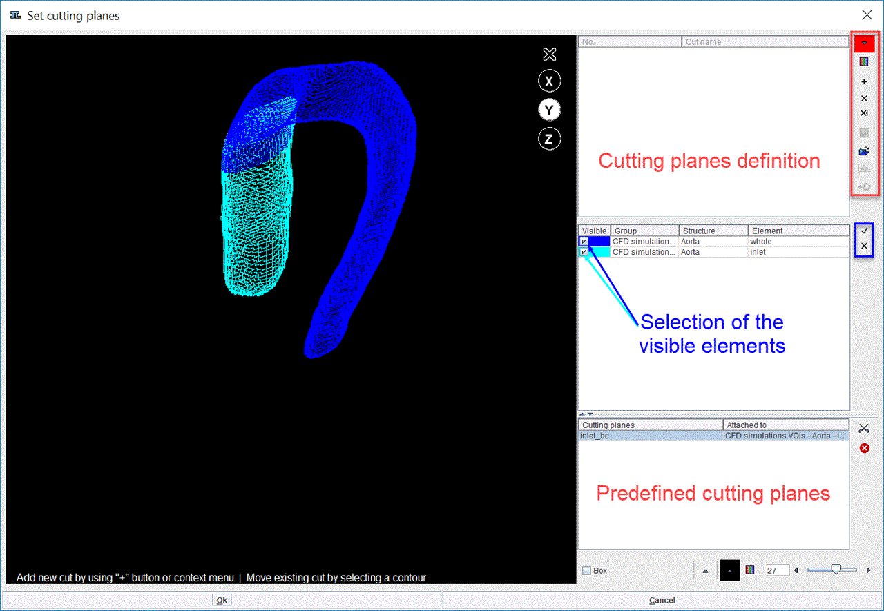
The window consists in an image area on the left and control and definition panels on the right. Note the divider buttons ![]()
![]() which can be used for enlarging/reducing the relative areas.
which can be used for enlarging/reducing the relative areas.
Elements List
The entries selected in the model tree are listed in the central panel on the right hand side of the window. Initially all the elements are displayed in the viewport area. Select/deselect the Visible check boxes for the structure of interest to change the appearance in the viewport. In the example above all elements are set to Visible.
Definition of cutting planes based on predefined cutting planes
When VOIs were added to the model as cutting planes, they were linked with the specified element in the model builder interface and consequently with the element entry in the model tree. The predefined cutting planes listed in the Cutting planes panel, bottom right, are linked to the entries in central elements panel. Select the entry in the list (e.g. inlet_bc) and activate the ![]() icon from the lateral task bar to cut the geometry with the selected cutting plane. The cutting plane is shown on the image on the linked geometry. The cutting plane definition panel, top right, list the copy of the predefined cutting plane as the first defined cutting plane.
icon from the lateral task bar to cut the geometry with the selected cutting plane. The cutting plane is shown on the image on the linked geometry. The cutting plane definition panel, top right, list the copy of the predefined cutting plane as the first defined cutting plane.
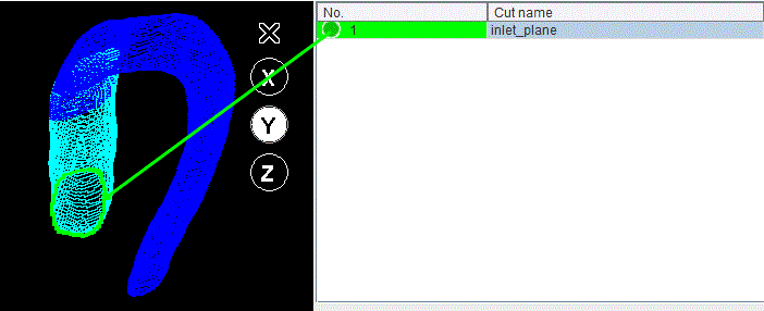
Double click in the Cut name field to assign a different name to the first cutting plane in the list: e.g. inlet_plane.
Definition of new cutting planes
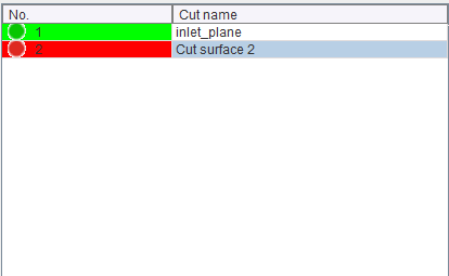
Activate the + icon in the taskbar to create a new cutting plane. A new entry appears in the top right panel with the default name Cut_Surface_2:
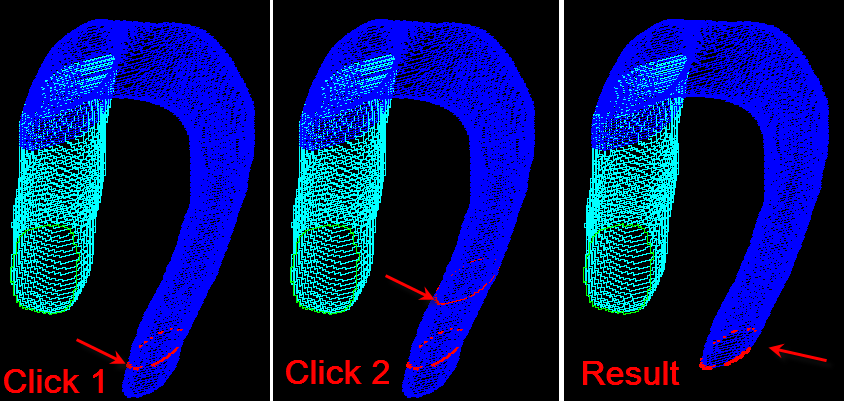
Successively click twice on the structure displayed in the viewport: the first click defines the cutting contour while the second click selects the part of the geometry to be used in the simulation. The opposite part of the geometry is discarded. The process is illustrated below:
Rename the new cutting plane to outlet_plane.
Saving the cutting planes
Saving of the cutting planes definition is started with the ![]() button in the lateral taskbar. It allows saving the entries in the list as *.cutPlane files. By simply retrieving those with the
button in the lateral taskbar. It allows saving the entries in the list as *.cutPlane files. By simply retrieving those with the ![]() button de definitions are recovered.
button de definitions are recovered.
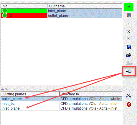
Alternatively, add the cut definitions to the model as cutting planes with the ![]() button. The cutting planes will be linked in the model with the element being cut and they will be appended to the existing predefined Cutting planes list as illustrated below:
button. The cutting planes will be linked in the model with the element being cut and they will be appended to the existing predefined Cutting planes list as illustrated below:
Modify a cutting plane
The process to modify a cutting plane is very similar to the definition of a new plane. First, the plane is selected in the list. Successively are requested two clicks on the image: the first click defines the new cutting contour while the second click selects the part of the geometry to be used in the simulation. The opposite part of the geometry is discarded.
Alternatively, discard the selected cutting plane from the definition list with the ![]() button. The
button. The ![]() button removes all the cutting plane definitions available in the list. Start the definition of a new cutting plane as described above.
button removes all the cutting plane definitions available in the list. Start the definition of a new cutting plane as described above.
Velocity profiles for the cutting plane definitions
When the creation of a CFD case is based on 4D Flow data the ![]() icon on the lateral taskbar becomes active. It allows calculating and visualizing the velocity profiles of the 4D flow data on the defined cutting planes. The result of such a calculation is shown below:
icon on the lateral taskbar becomes active. It allows calculating and visualizing the velocity profiles of the 4D flow data on the defined cutting planes. The result of such a calculation is shown below:
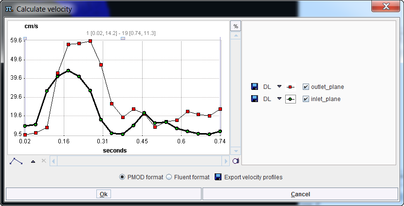
Save the velocity profiles with the Export velocity profiles button in one of the available formats: PMOD format, Fluent format. To close the window activate the OK button.
Note: It is mandatory that the 4D Flow data used in the creation of the CFD case are the same data used to build the currently selected anatomical model on the Model page.
Close the Preview interface with the OK button to generate the surface mesh. The calculation process may take a couple of minutes. The results are shown in a 3D window as illustrated below:
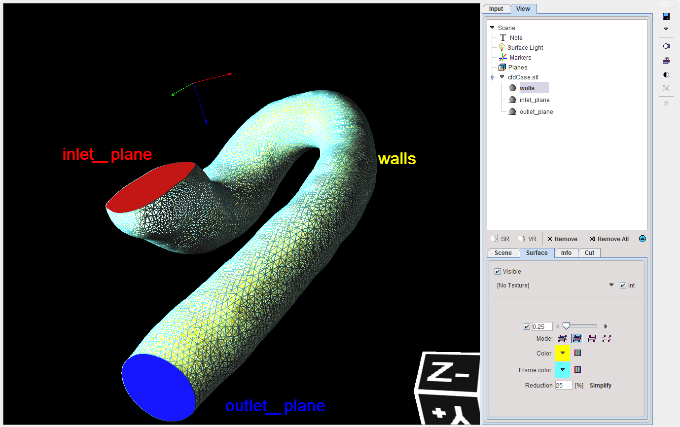
It allows exploring interactively the generated surface mesh. Close the window and continue with the VM creation.
The cutting planes will be used to define the boundary conditions for the CFD simulation.