The model is stored in the Structural model Path defined in the PGEM configuration settings. The model directory contains two folders and two files as illustrated below. :
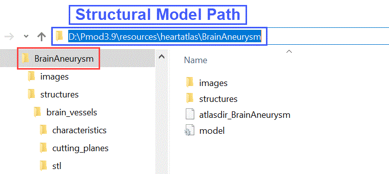
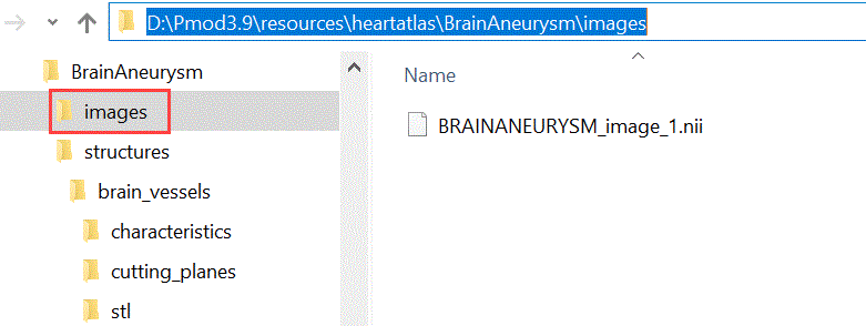
1.The image folder contains the image copied to the model folder as the reference image in niftii format.
2.The structures folder contains all the information related to the entries in the model tree.
3.The atlasdir_* file stores the frame time definition, reference image file information, settings used in the model builder interface.
4.The model file stores the information related to the PMOD version used to create the model and the definition of the model images .
The Structures Folder
The information related to each top level entry in the model hierarchy is organized in subdirectories with the same name. Their location is in the structures folder of the model directory as illustrated below:

The number of the subdirectories present in the structures folder equals the number of top level entries in the model tree. In the example above a single subdirectory is present: the cfd_structure. It indicates the model has a single top level entry.
The content of such subdirectory is shown below:
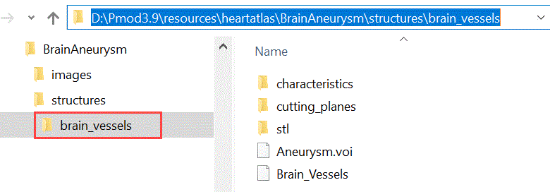
It contains:
1.The .voi file(s): the number of these files equals the number of middle level entries belonging to the same top level entry in the model tree. The name of the middle level entry in the model tree is used as the name of the .voi file: e.g. Aneurysm.voi.
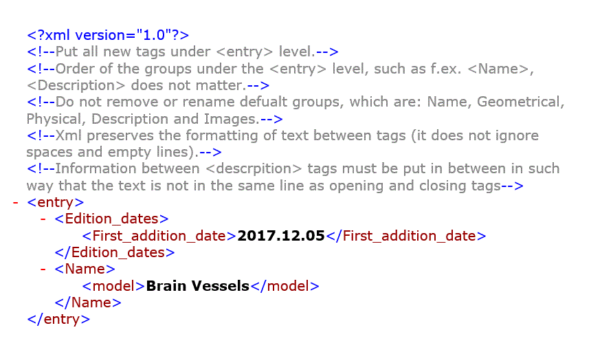
2.The .XML file: the name of the top level entry in the model tree is used as the name of the .xml file: e.g. Brain_Vessels. It stores information of the edition dates and the name of the top level entry in the model hierarchy as illustrated below:
3.The stl folder: contains the STL file of each middle level entry belonging to the same top level entry in the model tree. Particularly, for each .voi file the corresponding STL file is saved.
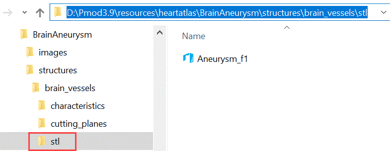
Please note that a suffix, e.g. _f1 is appended to the name: it corresponds to the Model frame definition in the Properties section in the model builder interface. This indicates that in the VOI adding procedure the Model frame field was set to 1. The static models (1 frame model) will always have Model frame set to 1. The STL files are used for 3D simplified preview of the model.
4.The cutting_planes folder: if VOI was added to the model as a cutting plane, such information is stored in a cutPlane file. The number of the files in the folder indicates the number of VOIs added as cutting planes. In the example illustrated below two VOIs were added as cutting planes:

The cutting plane is always linked with a low level entry in the model tree as described in the model builder interface. The name of the top level entry (Brain_Vessels) in the model followed by the middle (Aneurysm) and low level entry (Vessels) ones is used as the root name for the cutPlane file. The name of the VOI added as cutting plane is appended as suffix to the root name: e.g. _SingleContourVOI1.
5.The characteristics folder: stores the definitions provided as characteristics for each entry belonging to the respective top level entry in the model tree.
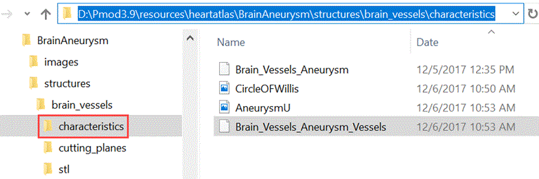
Such definitions are stored separately for each entry level in .xml files. The number of .xml files equals the number of middle and low level entries belonging to that specific top level branch.
The name of the top level entry in the model followed by the middle level entry one is used as the corresponding name for the Struture .xml file: e.g. Brain_Vessels_Aneurysm.
The name of the top level entry in the model followed by the middle and low level entry ones is used as the corresponding name for the Element .xml file: e.g. Brain_Vessels_Aneurysm_Vessels.
In the example below is illustrated the content of the Brain_Vessels_Aneurysm_Vessels:
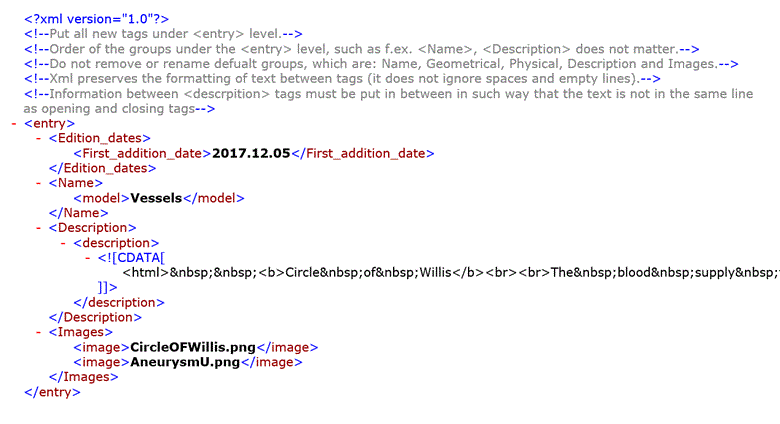
Each .xml file stores information about the edition dates, the level entry name encoded as described above, the text description and the images file names. The images, if defined, are stored as .jpg files with the specified name: e.g. CircleOFWillis and AneurysmU in the example above.
Note: To share a model with another PMOD user simply copy the model folder (e.g BrainAneurysm) to another PMOD installation in the Structural model Path defined in the PGEM configuration settings.