There are multiple places in PMOD where two different image sets can be combined into a fused image. Depending on the context, there are two arrangements for performing the image fusion.
Fusion Images not Visible at the same Time as the Source Images
In this layout only the fusion of two source series is shown.
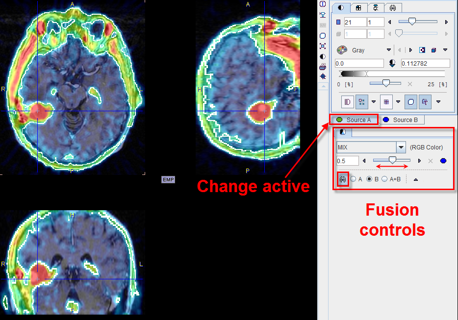
To adjust the presentation of either source image, select the appropriate tab Source A or Source B, and use the image controls. During such adjustments it will sometimes be helpful to only see the image you are working on, not the fusion. This can easily be achieved by moving the balance slider to one of the end positions left or right.
Separate Source and Fusion Images
In this layout both the input images and the fusion images are visible at the same time, as in the example shown below.
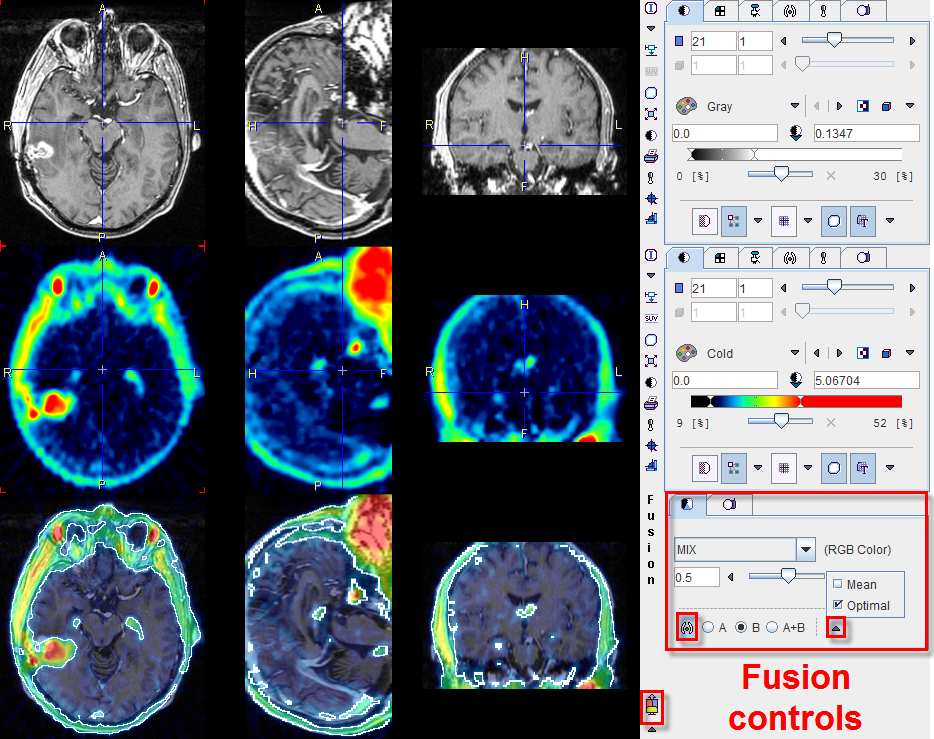
In this example the first row shows a T1-weighted MR image, and the second a matched 18F-Choline PET image with a highlighted tumor. To the right of the images the controls are available for changing the way how the images are displayed such as the color table, the thresholds, and the layouts. The third row shows the result of the fusion, depending both on the renderings of the source images, and on choice of the fusion controls located to the right.
Image Fusion Methods
The image fusion control

consists of three rows. The first row contains the selection(s) for choosing between the different fusion renderings, the second row allows enabling the balance to blend the contributions of the two images in the fusionthe, and the third row allows enabling the iso-contour overlays.
The fusion methods available are:
MIX |
Alpha Blending: weighted addition of the RGB values of both source images according to Example: |
MERGE |
RGB merging uses the maximal RGB value of both source images according to Example: |
OVL B |
Shows the images A as background and a part of the images B as the overlay. |
OVL A |
Is equivalent to OVL B except that the role of the images is reversed. |
WIN A |
Shows the images B (PET) as the background. When clicking into an image a rectangle appears which overlays the image A (MR). |
WIN B |
Shows the images A (MR) as the background. When clicking into an image a rectangle appears which overlays the image B (PET). |
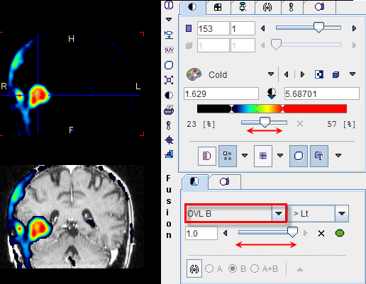
When the OVL A or OVL B methods are selected, different threshold settings are available in the selection to the right:
> Lt |
Only the pixels (in A for OVL A , in B for OVL B) with values above the lower threshold are displayed. This is the most useful setting when a hot lesion is to be blended into an anatomical image (see example for OVL B above). |
< Ut |
Only the pixels (in A for OVL A , in B for OVL B) with values below the upper threshold are displayed. |
>Lt Ut< |
Only the pixels (in A for OVL A , in B for OVL B) with values between the lower and upper threshold are displayed. |
<Lt Ut> |
Only the pixels (in A for OVL A , in B for OVL B) with values outside the lower and upper threshold are displayed. Note that only the first and last color of the selected color table are applied in this setting. A suitable selection in this configuration is the Split color table. |
An example of the <Lt Ut> method is shown below.
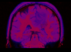
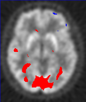
Image A represents normalized subject images, and image B the deviation from the normal pattern expressed as z-score values. The color table configuration of image B is
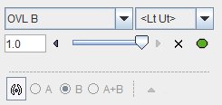
and the fusion settings
Only z-score values < -2 and > 2 are shown, without transparency. Because only the minimal and the maximal colors are use, the result has a binary character. Red are all pixels with an activation of more than two standard deviations, and blue all the pixels with the uptake reduced by at least two standard deviations. This is probably the most useful configuration for exploring the deviations from the standard pattern. |
|
Iso-contours in Image Fusion
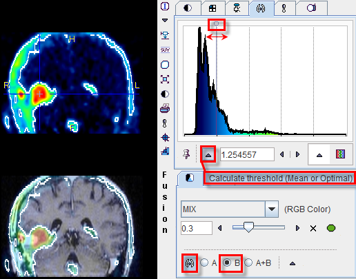
The contours radio box allows overlaying iso-contours derived from the source images A or B or both onto the fusion result. In the example below an iso-contour circumscribes the lesion clearly delineated in the FCH PET image. The iso-contour for the image B can be generated automatically selecting the Optimal option in the list in the Contouring tab. Setting the radio box B displays this contour in the fusion, which has been set to show mainly the MR image (A) by moving the balance slider to the left end. Another helpful application of the contours is in image matching.
